Wiadomość wysłana przez: Piękny Roman w Marca 03, 2017, 19:00
 |
| Image credit: NASA |
Theoretical work on lifting bodies began in the United States in the 1950s at National Advisory Committee for Aeronautics (NACA) laboratories. Early lifting bodies took the form of horizontal half-cones with rounded noses and flat tops. They were viewed mainly as steerable reentry bodies for nuclear warheads launched on Intercontinental Ballistic Missiles. By the end of the 1950s decade, however, as the 1958 Space Act transformed NACA into NASA and transferred to it most Department of Defense space facilities and projects, some engineers began to propose that lifting bodies serve as piloted reentry vehicles.
NASA opted to launch its astronauts in conical capsules rather than lifting bodies, but the lifting-body concept was by no means abandoned. In fact, it became a common element of U.S. space planning. In 1961, for example, both The Martin Company and the Convair Division of General Dynamics gave their proposed Earth-orbital/circumlunar Apollo spacecraft design lifting-body Command Modules.
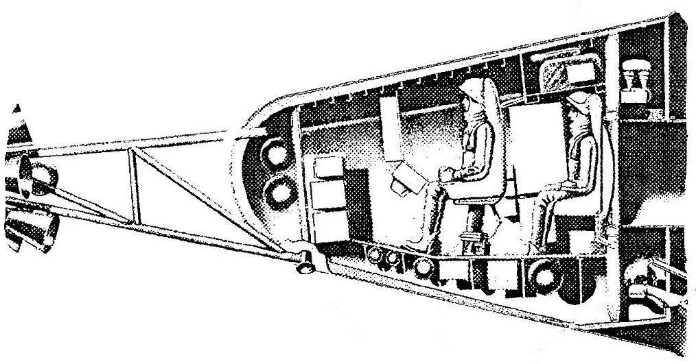 |
| Cutaway view of The Martin Company's lifting-body Apollo Command Module with portions of adjoining components visible (left - the Launch Escape Propulsion System; right - housing for the tunnel leading to the the Mission Module). This Command Module configuration, which Martin called Model 410, measured 12.5 feet long from its dome-shaped nose to its flat aft bulkhead and 12.5 feet across the widest part of its flat top. Image credit: The Martin Company/NASA |
Also in 1963, engineers and test pilots at the NASA Flight Research Center (FRC - later Dryden FRC; now Armstrong FRC) at Edwards Air Force Base (AFB), California, began piloted test flights of the M2-F1 lifting body (image at top of post). The lightweight M2-F1, a glider with a tubular steel frame and a mahogany plywood skin, was towed aloft a total of 77 times between March 1963 and August 1966 using a souped-up Pontiac Catalina convertible or a Douglas C-47/RD4 "Gooney Bird" aircraft. During some flights, the M2-F1 included a small rocket motor.
M2-F1 test flights showed that the lifting-body concept had promise, so NASA funded a program of lifting body development and test flights at FRC. It lasted from 1966 into the 1970s.
The M2-F1 confirmed, however, what 1950s experiments had shown: that lifting bodies become increasingly unstable as their speed decreases. With this in mind, in January 1964, Clarence Cohen, Julius Schetzer, and John Sellars, engineers with the aerospace firm TRW, filed a patent application for a piloted lifting-body spacecraft design that could accomplish what they called a "staged reentry." The U.S. Patent Office granted their patent (No. 3,289,974) on 6 December 1966.
Explaining the need for their invention, the TRW trio noted that the Mercury capsule, flown for the last time in May 1963, had given its astronaut occupant essentially no ability to alter his spacecraft's course after he fired its solid-propellant deorbit rocket motors. The astronaut could control the timing of his deorbit burn; an early burn would cause his capsule to plunk into the ocean short of its planned splashdown area, while a delayed burn would cause it to overshoot its target.
The Mercury astronaut could not use the atmosphere to steer his capsule any great distance away from the ground track of its orbit. In aerospace terms, the Mercury capsule followed a ballistic trajectory from deorbit burn to splashdown and had very limited cross-range capability. The ballistic trajectory subjected the Mercury astronaut to a deceleration load equal to about eight times the pull of gravity on Earth's surface.
The Gemini and Apollo reentry capsules, under development at the time Cohen, Schetzer, and Sellars filed their patent, would both feature an offset center of gravity about which they could roll while they moved at high speed. This would provide some lift and cross-range capability and help to limit deceleration loads. Both capsules would, however, become unsteerable and lose lift as they lost speed. Neither could not be guided toward a specific touchdown point after their parachutes deployed. Steerable triangular parawings had been proposed for both, but such systems were judged to be too complex, heavy, and prone to failure.
The flat-bottomed DynaSoar had been designed for both steerable, low-deceleration Earth atmosphere reentry and stability and steerability at low speeds; however, the Department of Defense space plane's flat belly and narrow-edged wings and fins made it difficult to cover with heat shield materials. Protecting the triangular glider adequately from reentry heating threatened to boost its weight so much that its ability to maneuver in the lower atmosphere might be compromised.
Cohen, Schetzer, and Sellars' staged reentry spacecraft was really two vehicles: a fairly conventional (though quite compact) two-seater jet plane and a lifting-body "pod." The delta-winged jet would nest within the upper part of the pod with its bubble cockpit canopy protruding from the lifting body's flat top surface.
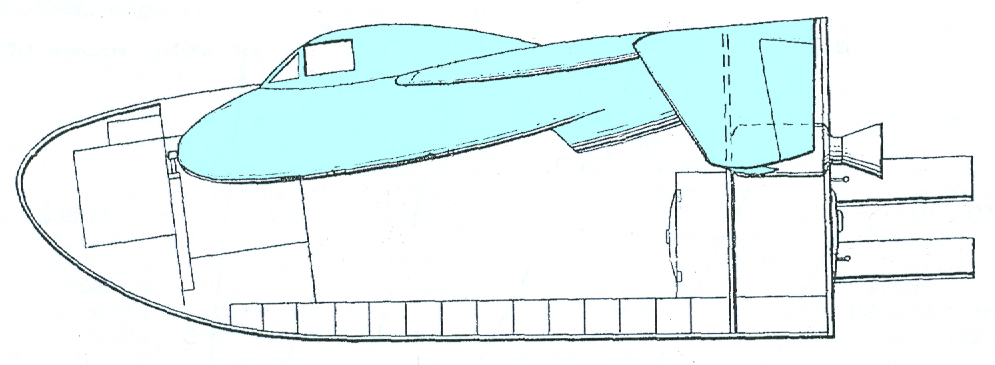 |
| Partial cutaway drawing showing the small jet plane nested within the lifting-body "pod." One of the jet's pair of downturned vertical stabilizers is visible. Image credit: U.S. Patent Office/TRW |
The pod would include two abort rockets and one deorbit/abort rocket. In the event of booster malfunction during first-stage operation, the astronauts could ignite the three aft-facing rocket motors to blast their spacecraft free of the booster. The crew couches would automatically move up rails into the jet airplane cockpit and hatches would close in the plane's belly, sealing the crew inside. After the abort engines expended their propellants, the crew would separate from the pod in the jet and descend to a controlled landing at the launch site or at any airport within several hundred miles of the abort point.
Assuming, however, that an abort did not become necessary, the two abort rockets would eject out the back of the lifting body immediately after second-stage ignition. Cohen, Schetzer, and Sellars estimated that ejecting the motors at that point in the flight would enable extra payload equivalent to 90% of the motors' mass to reach Earth orbit.
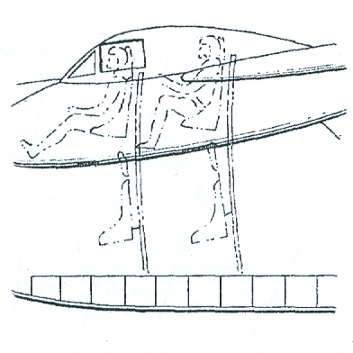 |
| Riding the rails: TRW's method for moving astronauts between the lifting-body pod and the jet airplane cockpit is reminiscent of Gerry Anderson's Thunderbirds. Image credit: U.S. Patent Office/TRW |
The internal arrangement of the pod was, however, of little real concern to the TRW engineers; in fact, they argued that the lifting-body pod might serve merely as a "jettisonable heatshield" fitted with deorbit and abort rocket motors and avionics. In that case, the jet airplane cockpit would comprise the staged-reentry spacecraft's sole crew volume.
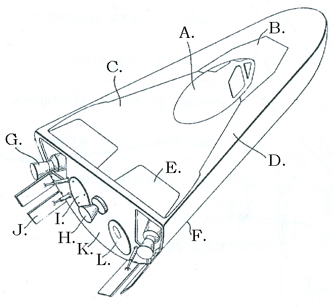 |
| TRW's staged reentry vehicle viewed from above and aft. A = jet airplane canopy; B = panel protecting jet airplane's nose; C = top surface of airplane fuselage and wings; D = lifting body top surface; E = jet airplane horizontal flap (1 of 2); F = lifting body underside; G = ejectable abort rocket motor (1 of 2); H = deorbit/abort rocket motor; I = parachute/landing aids compartment cover; J = movable control flap with actuator (1 of 4); K = flat aft bulkhead; L = airlock outer hatch. Image credit: U.S. Patent Office/TRW |
As the spacecraft entered the atmosphere, four aft-mounted movable control flaps would adjust ("trim") the amount of lift the lifting-body shape would generate. At first, the spacecraft would descend at a shallow angle designed to limit the deceleration felt by the crew to less than twice the pull of Earth's gravity. The crew could, if required, take advantage of the lifting body's cross-range capability to steer toward landing sites far north or south of their orbit ground-track.
 |
| The jet airplane detaches from the lifting-body pod. A = empty abort rocket compartment (1 of 2); B = experiment equipment and supplies; C = jet airplane separation rod with mounting pin (1 of 3); D = panel covering subsystems (for example, life support equipment); E = jet engine; F = vertical stabilizer (1 of 2); G = vertical control surface (1 of 2); H = rear landing skid (1 of 2). Image credit: U.S. Patent Office/TRW |
In some ways, this approach resembled the Soviet Vostok land landing method. Vostok, the first piloted orbital spacecraft, was a modified spy satellite. Its spherical reentry capsule landed at too high a speed for the cosmonaut inside to escape injury, so he or she ejected low in the atmosphere, deployed a personal parachute, and descended separate from the capsule.
The TRW engineers expected that the astronauts could land safely in the lifting-body pod if they could not separate from it in the jet plane. Assuming, however, that they separated as planned, they would glide away from the pod in the jet. After they ignited the jet's engine, they would fly around the landed pod to locate it for recovery personnel, then land at a predesignated airport. The subsonic jet would carry enough fuel to permit the astronauts to reach backup airports if, for example, weather conditions became uninviting at the predesignated landing site.
By the time the U.S. Patent Office granted Cohen, Schetzer, and Sellars their patent in December 1966, NASA FRC had begun flights of the M2-F2, an all-metal lifting body built by the Northrop Corporation. It was the first of NASA's "heavyweight" lifting bodies. The research aircraft was designed to be borne aloft beneath the wing of a specially modified B-52 and released so that it could glide to a landing on a dry lake bed runway at Edwards AFB. After it proved itself in gliding flight, pilots would ignite the M2-F2's single four-chamber XLR-11 rocket engine for high-speed and high-altitude tests.
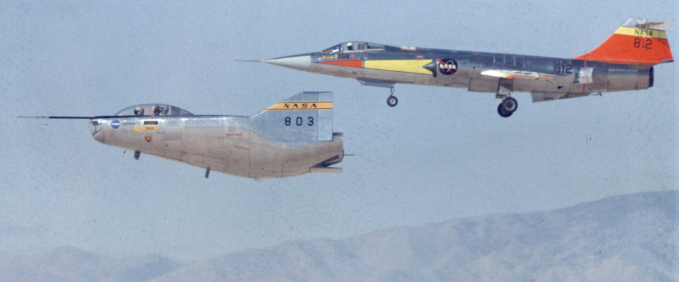 |
| NASA's M2-F2 heavyweight lifting body (left) flies beside an F-104 chase plane, 16 November 1966. Image credit: NASA |
Over the next three years, the M2-F2 was redesigned and rebuilt as the M2-F3, which included a third vertical stabilizer. The new centrally mounted fin markedly improved the aircraft's control characteristics.
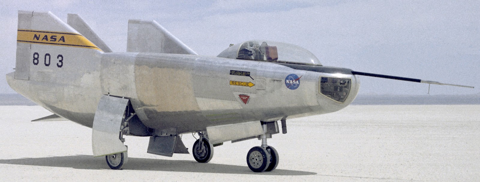 |
| The M2-F3 lifting body in 1970. Image credit: NASA |
Sources
Patent No. 3,289,974, "Manned Spacecraft With Staged Re-Entry," C. Cohen, J. Schetzer, and J. Sellars, TRW, 6 December 1966
Apollo Final Report: Configuration, ER 12004, The Martin Company, June 1961
Wingless Flight: The Lifting Body Story, R. Dale Reed with Darlene Lister, NASA SP-4220, The NASA History Series, 1997
Wingless Flight: The Lifting Body Story, R. Dale Reed with Darlene Lister, NASA SP-4220, The NASA History Series, 1997
International Rescue Thunderbirds Agents' Technical Manual, Sam Dunham with Graham Bleathman, Haynes Publishing, 2012
Source: A 1964 Proposal for a Small Lifting-Body Shuttle with "Staged Reentry" (http://)